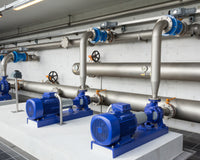
Circulation pumps and system equipment are the two pillars of every boiler room. The pump forces the fluid to circulate, while the equipment determines whether that circulation is stable, safe, and adjustable. At Dambat, we design and supply both elements under the IBO and IPRO brands, so in this publication we have compiled the practical differences between the series, designation conventions, and the principles for selecting system equipment components that installers ask us about most often.
This text is intended for installers, service technicians, and designers. Instead of generalities, we show what really distinguishes a pump with a differential-pressure controller from a three-speed pump, when a return protection group replaces a set of individual fittings, and why some heating system equipment—for example, safety valves or expansion vessels—is selected before the pump rather than after it. Our reference point is a closed central heating system in a single-family home, but most of the principles also apply to larger heating systems, multi-zone substations, and industrial circuits.
Heating system equipment is not an addition to the pump—it is a prerequisite for its proper operation. In our diagrams, we divide system equipment into three groups: hydraulic (valves, manifolds, hydraulic separators), safety-related (safety groups, expansion vessels, thermal protection devices), and measuring and control equipment (sensors, controllers, pressure gauges). This division makes it easier to complete an order and quickly check what is missing from the heating substation.
Circulation and hot-water circulation pumps — where one role ends and the other begins
In workshop practice, both terms are sometimes used interchangeably, but in technical documentation we consistently distinguish between them. A circulation pump operates in a closed heating circuit: it overcomes the hydraulic resistance of pipes, radiators, coils, and fittings, rather than the head. A circulation pump, on the other hand, operates in an open hot-water loop and maintains the temperature in the circulation pipe so that the user does not have to let water run from the tap while waiting for it to heat up.
The consequences of the selection are very specific. In a closed central heating system, a standard cast-iron housing is sufficient because the water circulates continuously and is not replaced. Where a domestic hot water system operates with a continuous inflow of fresh water, a cast-iron housing is not the right choice—that is why we use models with bronze or steel housings for circulation, such as BETA 2 25-60/130 with a bronze housing, or dedicated low-power circulation pumps. A domestic hot water system with circulation operates with low resistance, so the circulation pump is selected based on the loop length and the pipeline's heat losses, not the power of the heat source.
Domestic hot water: circulation pump and circulation loop
Domestic hot water circulates in a loop with low resistance, so the required pump specifications are surprisingly modest. Our EPRO 15-15 PLUS circulation pump consumes 3–9 W, provides a head of 1.2 m and a flow rate of up to 10 l/min, operates in the range of 2–95 °C (TF95) at a system pressure of up to 1 MPa, has an IP44 protection rating and insulation class F. The E-IBO PRO 15-14 model has a 72 mm port spacing, a ½" thread, a digital panel and a programmer that allows up to three independent operating periods to be set per day. For simpler applications, we offer EBO 15-15, while for buildings with larger loops—we offer higher-power units from the domestic hot water circulation pump range
Domestic hot water does not need to circulate around the clock. A timer or a thermostat on the return line of the loop limits pump operation to the hours of actual consumption, which matters more in multi-family buildings than the motor power itself. We wrote more about this in the guide how to use domestic hot water circulation effectively and in the article about circulation pumps in domestic hot water systems
How to read the designations and how our series differ
The designation 25-60/180 describes three things: the connection diameter (DN25), the maximum head in metres of water column (6 m), and the centre-to-centre distance between the ports in millimetres (180 mm). This third parameter determines whether the pump can be replaced in an existing installation—when modernising, it is worth checking it before ordering, because the difference between the /130 and /180 versions means that a section of the pipeline must be rebuilt.
| Series | Brand | Specifications | Typical application |
|---|---|---|---|
| PANDA | IBO | Permanent-magnet motor, differential pressure controller, AUTO mode and constant speeds HS1–HS3, energy consumption display, union fittings included | Domestic central heating system, replacement of a three-speed pump |
| OVI / IVO | IBO | Compact electronics, power consumption of 5–45 W, control panel with venting function | Single-family boiler rooms, DN25/DN32 connections |
| NOVA / NOVA MAX | IBO | Class A, EEI ≤ 0.23; NOVA MAX with DN40/DN50/DN65 flanged connection and a head of up to 12 m | Larger heating systems, multizone circuits, multi-family buildings |
| MAGI 2 / MAGI H / MAGI MAX | IBO | Differential-pressure regulator, 8 operating modes, top-mounted panel, range 2–110 °C, 36-month warranty | Systems with variable flow, high resistance (MAGI H—12 m at DN25) |
| BETA 2 | IBO | EEI ≤ 0.23, 8 modes: ECO, PP1/PP2, CP1/CP2, and I/II/III; BR version with a bronze body | Central heating, solar systems, domestic hot-water circulation (BR version) |
| AMG / AMG SOLAR | IBO | PWM signal support, control cable included | Cooperation with a boiler controller, solar systems |
| API PWM | IPRO | PWM frequency converter, EEI ≤ 0.23, 8 modes, range 2–110 °C | Installations controlled by an external regulator, installation in pumping groups |
| IGDL | IBO | Multistage in-line pump, 0.37–1.5 kW, 230 V and 400 V versions, DN40/DN50 connections | Pressure boosting and circulation in high-rise buildings, process circuits |
| IPML / IPTL | IPRO | Glanded pumps from 0.55 kW to 18.5 kW, 230 V and 400 V, DN32–DN100 flanged connections | Industrial installations, district-heating substations, cooling circuits |
Operating mode names are worth understanding literally, because they determine actual power consumption. Proportional-pressure curves (PP1/PP2) are used in systems with thermostatic radiator valves, where the flow changes. Constant-pressure curves (CP1/CP2) are suitable for underfloor heating with a manifold. Constant-speed modes (I/II/III) are reserved for systems with a consumer whose resistance remains unchanged and for diagnostics. Modern heating systems operate with variable flow, so a pump running at a constant speed almost always operates outside its optimum point: it either throttles the flow or creates noise at the valves. If a central-heating system was expanded in stages, it is worth calculating the resistance of the longest circuit before selecting a mode, rather than merely adding up the radiator outputs.
You can find the full overview in our circulation pump category and in the article about the advantages of electronically controlled pumps.
Controllers, inverters, and electrical accessories for boiler rooms
Controllers are the component installers most often cut costs on—and most often revisit after the first season. Our S-150 central-heating pump controller switches the pump on when the set temperature is exceeded and switches it off when the temperature falls below the shutoff threshold, within a range of 0–99 °C, with two LED displays, a thermostat function, and an anti-stop function that periodically starts the rotor after a longer period of inactivity. This solution is designed for boilers whose pump is not controlled by the source's automation system.
Room controllers are a different class of devices: they respond to the air temperature in a room and usually control the heat source or zone actuators. Room controllers do not replace a pump operating controller—they measure a different variable and have a different time constant. In mixed systems, we use both: the room thermostat determines demand, while the controller at the boiler protects the heat exchanger and pump.
As a manufacturer of electrical equipment for pumps, we also supply SPP and SPD control cabinets (for one and two pumps), M-series motor protection devices for ratings from 0.37 kW to 7.5 kW, as well as pressure switches and other control and protection equipment. Variable-frequency drives are a separate group: in our range, they regulate the operating conditions of water pumps—they have nothing to do with photovoltaic inverters, although the variable-frequency technology is shared. We describe them in more detail in the article about smart pumps with variable-frequency drives.
Electrical equipment installation and division of responsibilities
Installing electrical equipment in a boiler room requires the appropriate authorizations—and this is no mere formality. The electrical installation components supplying the pump must be selected according to the starting current, line length, and cable routing method, while a safe electrical installation includes a residual-current device, proper grounding, and a separate circuit for higher-power heating equipment. We begin installing the electrical equipment by checking that the pump circuit is separate and protected by the correct circuit breaker. For calculations, we provide a cable cross-section calculator and a maximum cable length converter, while the context is explained in the article why cable length and diameter matter.
The functions of electrical equipment are divided into three groups: control equipment (controllers, regulators, actuators), protective equipment (thermal switches, overcurrent protection, dry-run sensors), and measuring equipment (temperature sensors, pressure switches). A plumbing installer may install ready-made, factory-wired components, but modifying circuits or repairing electrical installations is the responsibility of an electrician with the appropriate qualifications. This division of responsibilities is part of what we mean by professional installation. The installation of electrical equipment should conclude with a measurement report—without one, it is difficult to determine later whether a fault resulted from the device or the power supply.
The functions of electrical equipment should also be checked against the documentation. Before installing electrical equipment, check the IBO instructions for the permitted supply parameters, IP rating, and required distances from hot components—these data vary between product series and determine whether the device can be installed in a cabinet.
Mixing, thermostatic, and cooling valves—regulating water temperature and protecting the heat source
Mixing valves ensure that water at the correct temperature reaches the heat consumer and that sufficiently warm water returns to the boiler. Regulating the return water temperature is not a matter of comfort but of heat exchanger durability: in solid-fuel boilers, condensation on cold heat exchanger surfaces leads to low-temperature corrosion and tar buildup.
Our MIX TVR thermostatic mixing valves mix cold return water with hot boiler water and maintain the return temperature at the valve's opening temperature. An important design consideration is that, thanks to automatic flow control at the bypass inlet, they do not require an additional balancing valve. Thermostatic valves of this class are available with 25 and 32 connections and at several opening temperatures.
In larger systems, mixing valves are implemented as three-way valves with an actuator. Our MIX3 DN40 is a mixing and diverting valve for central heating, cooling, and domestic hot water systems, controlled manually or automatically by an actuator—in our installation recommendations, we specify the IBO STER D actuator. The required supply temperature is achieved by mixing the boiler medium with the return medium, which is why mixing valves have a dual role here: they regulate the heat consumer and protect the heat source.
At the manifold, mixing valves allow the temperature to be lowered only for the underfloor heating circuit while maintaining high-temperature supply to the radiators. This is the most common reason why two different types of fittings are found in a single installation and why mixing valves are among the installation equipment components that should not be selected at the end of the design process.
A ready-made assembly is the IBOMAT API return protection group—a TSV3B thermostatic valve, pump, insulation, and thermometer in one housing for installation on the return pipe of a boiler or fireplace with a water heat exchanger. The variants differ in opening temperature and the maximum supported boiler output: 45 °C for up to 46 kW, 50 °C for up to 42 kW, and 55 °C for up to 36 kW. The control range is +5 °C above the opening temperature, the power supply is 230 V/50 Hz, the operating temperature is 5–95 °C, the maximum pressure is 6 bar, and the connections are 3× GW 1". The medium may be water or a glycol solution of up to 50%.
Cooling valves, a ball valve with an actuator, and check valves
Cooling valves protect against overheating of the heat source. Our IBV 2 has a brass body and two thermostatic elements: when the limit temperature of 97 °C ±2 is reached, it opens the drain valve and simultaneously opens the valve supplying water from the mains. It is intended for boilers with a maximum output of 500 kW, with final cooling of up to 100 kW in accordance with EN 303-5:2012, and must not be installed with the head facing downward. We emphasize clearly—including in the product data sheet—that cooling valves do not replace a safety valve.
For switching between circuits, we use MIX 2 UNI CONTROL: a three-way ball valve with a 230 V actuator, supporting two- and three-point control, with manual mode and retention of the last position in the event of a power failure. It is available in DN20, DN25, and DN32, with internal and external thread versions. This ball valve serves as a diverting or switching valve, including in heat pump systems—our products are compatible with such installations, although we do not manufacture heat pumps ourselves. Details are described in our article on the IBO MIX2 zone valve.
Check valves serve two functions in a boiler room: they block gravitational flow through an inactive circuit and protect the pump from reverse flow after shutdown. In systems with several heat sources, check valves are essential for reliable automation operation—without them, heat “escapes” into a circuit that should be inactive. We have compiled the types and selection guidance in our article on check valves in the IBO range, and the DN25/DN20 service valve is also useful for replacing a pump without draining water from the system.
Central heating pump groups, manifolds, and hydraulic separator
Pump groups are ready-made installation equipment components in which the sequence of the fittings has been determined at the factory. Central heating pump groups shorten installation time and eliminate errors in the sequence of the fittings. Our GP PRO groups are available in BO, 3D-S, and 3D-T versions, and the set includes two shut-off valves with thermometers and half-unions, a three-way valve with a half-union, a mixing valve actuator, a return connection, and front and rear insulation. The spacing is compatible with 25-60/180 pumps, so the group can be ordered with an API 25-60/180 pump or another unit with the same spacing.
We connect central heating pump groups to manifolds for 3+2 circuits (2+1 and 4-circuit versions are also available) and to the SP-S horizontal hydraulic separator. The separator hydraulically separates the boiler circuit from the heating circuits: the boiler pump operates within its optimal range, while the pumps in individual circuits can change the flow without disrupting the heat source. The limiting parameters are usually 90–110 °C and approximately 6 bar—the exact values should always be checked in the documentation for the specific model. An alternative for use with a manifold is the GP MIX T 235 mm, for which the pump is selected separately.
Expansion vessels, filters, and pressure gauges—heating system equipment that protects the pump
Expansion vessels compensate for changes in the volume of the fluid as it heats up. They are components of the installation equipment that we select before choosing the pump—as they affect the pressure in the system, not the other way around. Without them, pressure increases, the safety valve opens, the system loses water, and each refill introduces oxygen and salts into it—which accelerates corrosion and causes the pump to become airlocked. Our BASIC diaphragm expansion vessels for central heating and domestic hot water range from 8 to 100 liters and are available in wall-mounted and freestanding versions; an example is the BASIC 12 C.H. diaphragm expansion vessel.
It is worth standardizing the terminology, as it is often a source of mistakes in orders: a diaphragm expansion vessel, diaphragm vessel, and expansion tank are essentially the same component of a closed heating system. An open expansion vessel (the former vessel located at the highest point of the system) is a completely different solution and is now found mainly in modernization projects. Capacity is calculated based on the volume of water in the system, operating temperature, and pre-charge pressure — our expansion-vessel sizing calculator is used for this purpose. Expansion vessels with insufficient capacity are one of the most common causes of cyclic water discharge through the safety valve.
We supply safety valves as complete groups: IGB INOX 3/4" with a steel body, MGB in a brass version, and SGB. One assembly contains a pressure gauge, automatic air vent, connection for a diaphragm expansion vessel, and safety valve; the INOX version also includes a service valve. We select safety valves so that the opening pressure is lower than the boiler's maximum permissible pressure — variants of 1.5, 2.5, 3, and 6 bar are available. For the SGB group, the limit values are 6 bar, 90 °C, glycol up to 50%, a 0–10 bar pressure gauge, and a maximum diaphragm vessel diameter of 340 mm.
A closed central-heating system requires both an expansion vessel and pressure protection — these are not alternatives but a pair of components that work together. We select the heating-system equipment in this area based on the maximum operating temperature and the permissible pressure of the weakest component in the system, which is usually the boiler or storage tank.
Filters, pressure gauges, and pipe diameters
The magnetic filter captures iron particles circulating in the system, which would otherwise grind hydraulic components, block actuators, and accumulate in the impeller. Our I-003 3/4" magnetic filter operates at up to 8 bar and 90 °C, filters particles ≥ 500 μm at a flow rate of up to 100 l/min, and has a magnet strength of 9,000 Gauss. The full range includes magnetic separators and iron-removal filters; we explain the context in the article on protecting heating systems with magnetic filters and in the text on why a filter that protects the pump is needed in central-heating and domestic-hot-water systems.
Pressure gauges are the cheapest diagnostic tool in a boiler room and the one most often overlooked. We offer 40 mm radial pressure gauges with a bottom 1/4" connection in ranges of 0–2.5, 0–4, and 0–10 bar — such as the 0–4 bar radial pressure gauge; 60 mm axial pressure gauges with a rear connection are also available. The principle for selecting the range is simple: the operating pressure should fall in the middle of the scale because reading accuracy decreases at the ends. Two pressure gauges — before and after the filter or before and after the pump — make it possible to assess resistance without dismantling the installation. More information is available in the article about pressure gauges and water pressure measurement.
Pipes and their diameters determine how much work remains for the pump. Undersized pipes mean high resistance, flow noise, and pump operation at a higher curve. Oversized pipes, in turn, extend the installation’s response time and increase its water capacity, which translates into larger expansion vessels. During modernizations, when steel, copper, and plastic pipes meet in a building, our tools are useful: pipe diameter converter, the article DN to inches, and the guide how to choose the right pipe diameter.
What we do not manufacture — but what still affects pump operation
Not all installation equipment in the boiler room comes from us, and we do not want to pretend otherwise. Below are four groups that installers ask about when placing orders, together with information on how they interact with our devices.
Draft regulators. In solid-fuel boilers, draft regulators mechanically control the air supply without electrical power. This has a consequence that is easy to forget: when the power goes out, the draft regulators continue operating while the pump stops. The boiler continues transferring heat to water that is no longer circulating. That is why, in such systems, we design heat dissipation that does not depend on electricity — a gravity circulation system or IBV 2 cooling valves — and do not treat the controller as a safety device. Draft regulators are not part of our range, but their presence tells us that the installation requires return protection and thermal protection. It is also worth remembering that incorrectly adjusted draft regulators cause temperature fluctuations which, with a constant-speed pump, end in the safety valve opening cyclically.
Uninterruptible power supplies. Uninterruptible power supplies for circulation pumps in solid-fuel boiler rooms are a safety feature, not a convenience. We do not manufacture them, but we have one important recommendation: our electronic pumps with permanent-magnet motors and frequency converters should be powered by systems with a pure sine-wave output. Uninterruptible power supplies with a modified (“quasi-sine”) waveform may be accepted by older three-speed pumps, but with electronic pumps they can cause overheating and control errors. Before selecting an uninterruptible power supply, check the permissible power supply parameters for the model in the manual and account for the starting current, which is higher than the operating current. Uninterruptible power supplies should be selected for the total load—pump, controller, actuators—not just the pump’s nominal power.
Electric heating elements. Electric heating elements in buffer tanks and domestic hot water tanks are typical electric heating devices, which we also do not manufacture. However, they affect pump selection: electric heating elements operating in a tank change the temperature distribution, and in systems with circulation they mean maintaining the temperature in the loop for longer. From an electrical perspective, electric heating elements with a capacity of several kilowatts require a separate circuit and a properly selected conductor cross-section—another reason why the boiler room’s electrical installation should be designed together with the hydraulic system, not afterward. If electric heating elements appear in the design as a peak heat source, it is worth checking the selection of the expansion vessel and safety group for the new operating temperature.
Stainless steel chimneys. Stainless steel chimneys and chimney liners are a separate field requiring separate qualifications—they are not part of our product range. For pump selection, only one conclusion matters: stainless steel chimneys installed when replacing a boiler usually go hand in hand with a change in the system’s operating temperature, which changes the required flow rate and head.
Equipment component installation—the sequence matters
Installing equipment components in a boiler room is rarely hindered by a lack of knowledge; more often, it is a lack of space. Below is the sequence we use in our diagrams and follow in the project documentation available in the DWG files for projects.
- Filter before the pump. Always on the inlet, never behind the impeller. Install the magnetic and mesh filters so they can be accessed for cleaning without removing the pump.
- Isolation valves on both sides of the pump. This means replacement does not require draining the entire system—this is where a service valve is useful.
- Shaft horizontal, terminal box accessible. Circulator pumps are installed with the shaft in a horizontal position, regardless of whether the pipeline runs vertically or horizontally. The arrow on the housing must correspond to the direction of flow.
- Air venting at the highest point. Air in the impeller causes noise, reduced performance, and dry running. We describe the procedure in the guide to venting a central-heating pump.
- Safety group and expansion vessel on the return line. Safety valves must be installed without any shut-off fittings between them and the heat source—this is a requirement that must not be circumvented.
- Pressure gauges in visible locations. A pressure gauge hidden behind insulation cannot perform its diagnostic function.
It is also worth planning the installation of accessories with servicing in mind: clearances, access to unions, and the possibility of supporting the pipeline determine how long replacement will take later. Professional installation is recognized precisely by the fact that the pump can be replaced in fifteen minutes, not half a day. We have compiled typical signs of errors in the article about incorrect circulator pump operation, while hydraulic phenomena are discussed in the articles about water hammer and cavitation.
Step-by-step selection and the tools we use
A central-heating system does not require complicated calculations if we follow the correct sequence. Below is the process we go through with installers when selecting equipment:
- Flow rate. We calculate it from the heat output of the emitters and the difference between the supply and return temperatures—it is the starting point, not the boiler’s output.
- Resistance. We add up the losses in the pipeline, fittings, and heat emitter; our pressure-loss and performance tables and volumetric flow calculator are helpful.
- Duty point. We check that it falls within the middle section of the selected pump’s characteristic curve—not at its edge.
- Control mode. We select the curve according to the installation type: proportional for thermostatic valves, constant for underfloor heating.
- Accessories. We complete the assembly with mixing valves, check valves, expansion vessels, pressure gauges, controllers, and safety devices.
- Verification. After the first season, it is worth comparing actual power consumption—the pump replacement savings calculator and the article how to calculate a pump’s hourly electricity consumption can help.
We have compiled the remaining conversion tools—pressure units, NPSH and cavitation risk, and water demand—in one place, in the conversion tools and calculators section. We provide training materials in the IBO Academy, and definitions of terms in the hydraulic terms glossary.
Beyond the boiler room—the rest of our range
Our heating systems are one of several areas of our business. In addition, we manufacture and supply submersible borehole pumps, surface pumps, submersible pumps, and pressure booster sets. These groups operate in the raw, untreated water zone, before the treatment process—they are not water-treatment devices and do not confirm that the water is fit for consumption. If water from a private water source is to be used for drinking or household purposes, the user should ensure appropriate treatment and quality control at the point of use.
A separate group comprises condensate pumps, useful with condensing boilers and air conditioning, as well as installation equipment and accessories, including the BY-PASS KOMBI 25-3 connection valve, a Multiblock-type valve for connecting water softeners and filtration systems. You can find an overview of the entire range in the brand categories for IBO and IPRO.
Purchase, warranty, and documentation
High equipment quality is verifiable through documents, not slogans, which is why we make product data sheets, manuals, and declarations publicly available. In 2015, the IBO brand received the silver “Consumer Quality Leader” emblem in the circulation and circulation pump category, but specific data is more useful when making a selection: energy class, EEI, temperature range, and connection spacing. In our understanding, high equipment quality means consistent dimensions between batches and the availability of spare parts years later—not a declaration in a catalogue.
High-quality accessories reveal their value only during the second or third inspection: that is when you can see whether the unions can still be unscrewed, whether the seals have retained their flexibility, and whether a replacement cartridge or impeller is still available for the device. That is why we maintain separate parts catalogues for each brand.
We sell our equipment through a network of partners—you can find the list on the partner stores and wholesalers page, and we describe the ordering process in the article how to buy an IBO pump. We provide warranty and post-warranty service in Adamów 50 near Grodzisk Mazowiecki—details are available on the service page, in the article about complaints and spare parts, and in the IBO spare parts catalogue. If you have technical questions, please contact us—we can help select a pump and accessories for your specific system based on its parameters, not guesswork.
FAQ—circulation pumps and installation accessories
What is the difference between a circulation pump and a hot-water recirculation pump?
A circulation pump forces the fluid to circulate in a closed heating circuit and overcomes only the hydraulic resistance. A hot-water recirculation pump operates in a domestic hot-water loop, where water is replaced, so bronze or steel housings are used instead of cast iron. Hot-water recirculation pumps have much lower ratings—typically a few watts and around one metre of head.
What does the symbol 25-60/180 on the pump housing mean?
The first number is the connection diameter (DN25), the second is the maximum head in metres of water column (6 m), and the third is the centre-to-centre distance between the connections in millimetres (180 mm). When replacing a pump, checking the centre-to-centre distance is crucial because the /130 and /180 versions are not interchangeable without rebuilding the pipeline section.
Which operating mode should I choose: proportional or constant pressure?
Proportional pressure (PP) is suitable where the flow changes, that is, in radiator systems with thermostatic heads. Constant pressure (CP) is suitable for underfloor heating with a manifold and long loops. Constant-speed modes should be reserved for diagnostics and systems with unchanging resistance.
Can the pump be installed in any position?
The motor shaft must remain in a horizontal position—this applies to both vertical and horizontal pipelines. The terminal box should be accessible, and the flow direction must match the arrow on the housing. Positioning the head with the terminal box facing downward may flood the electronics due to condensation.
Why is a return protection group needed if the boiler has a controller?
A controller responds to measurements and requires a power supply, while thermostatic mixing operates mechanically and immediately. The IBOMAT API group maintains the return temperature above the condensation threshold, protecting the heat exchanger against low-temperature corrosion and tar buildup. In the 45, 50, and 55 °C variants, it supports boilers rated up to 46, 42, and 36 kW, respectively.
Does a thermal discharge valve replace a safety valve?
No. The IBV 2 dual-function valve discharges excess heat after the temperature exceeds 97 °C ±2, opening the drain and water replenishment functions, but this is thermal protection, not pressure protection. Protection against excessive pressure increase is provided by a separate component, supplied by us in complete IGB, MGB, and SGB safety groups.
How do I select the capacity of a diaphragm expansion vessel?
Three pieces of information are needed: the amount of water in the installation, the maximum operating temperature, and the initial pressure and valve opening pressure. The BASIC series includes capacities from 8 to 100 liters in wall-mounted and floor-standing versions. We provide a capacity-sizing calculator on our website.
Can an electronic pump operate with an uninterruptible power supply?
Pumps with permanent-magnet motors and frequency converters require a power supply with a clean sine-wave output. A modified waveform may cause overheating and control errors. Before purchasing, check the permitted power-supply parameters in the instructions and take into account the starting current and the load from the controller and actuators.
Where should I install the magnetic filter, and how often should I clean it?
Install the filter on the pump inlet, in a location that allows cleaning without removing the device. The I-003 model operates at up to 8 bar and 90 °C with a flow rate of up to 100 l/min. Cleaning frequency depends on the condition of the installation—in older steel systems, it is worth scheduling the first inspection after a few weeks of operation.
Which pressure gauge range should I choose for a domestic boiler room?
The range should be selected so that the normal operating pressure falls in the middle of the scale—for a typical domestic installation, ranges of 0–4 bar work well, while 0–10 bar is suitable for higher pressures. The radial version has a bottom connection, while the axial version has a rear connection, making installation easier in confined spaces.
What is the warranty, and where can I find the technical documentation?
The warranty period depends on the series—for example, MAGI 2 pumps are covered by a 36-month warranty, while IBOMAT API groups have a 24-month warranty, calculated from the date of purchase. We provide instructions, CE declarations, and design files in the downloads section, and our service center is located at Adamowo 50 near Grodzisk Mazowiecki.