Why do the length and diameter (cross-section) of a cable matter — especially at higher voltage?
A simple beginning
Every electrical cable is a “road” for current. If the road is too narrow (a thin cable) or too long, problems arise – just as on a narrow, long road, where traffic jams form and cars travel more slowly. In electrical installations, these “traffic jams” are voltage drops, energy losses, and heating of the conductors.
That is why you must always choose a cable with the appropriate diameter (cross-section) and length for the specific installation.
Why is this so important?
1. Voltage drops
The longer the cable, the greater the resistance it creates. The current has to “push through” the conductor, causing a voltage drop at the end of the cable.
➡ Example: if a device needs 230 V, but only 210 V reaches it through a long, thin cable, it may operate less effectively, wear out faster, or fail to turn on at all.
2. Heating of conductors
Too small a cross-section = excessive current density. The cable starts to heat up.
➡ This means a risk of fire, as well as a shorter installation lifespan.
3. Safety and interference
Every cable generates an electromagnetic field and acts somewhat like an antenna. The longer it is, the more easily it picks up interference from its surroundings and may affect other devices. Therefore, special cable designs are used for higher voltages (e.g., shielded cables, twisted pairs, and coaxial cables).
4. Electrical length and wave phenomena
At very high frequencies and voltages, an ordinary cable stops behaving like an “ordinary conductor.” It starts acting like a transmission line or antenna, where signal reflections and energy losses occur. At that point, the following become crucial:
- constant impedance,
- signal propagation speed (the so-called velocity factor),
- appropriate conductor geometry.
Cables and voltage – the basic classification
- Low voltage (up to 1 kV) – typical domestic and industrial installations.
- Medium voltage (1–36 kV) – distribution between transformer substations.
- High voltage (above 36 kV) – transmission of energy over very long distances.
The higher the voltage and the longer the distance, the larger the conductor cross-section that must be used.
A cable is a “road” for current. When this road is too narrow (small cross-section) or too long, voltage drops occur, conductors heat up more, and equipment may operate unstably. Choosing the right length and cross-section improves safety and limits energy losses.
In the simplest terms: three consequences of poor selection
- Voltage drop—the longer the conductor, the greater the resistance and the lower the voltage at the end of the line. This results in poorer equipment performance (with high loads, it may even prevent startup).
- Overheating—a cross-section that is too small for a given current means a higher current density and more heat, reducing service life and increasing the risk of fire.
- Interference—long cables act somewhat like antennas: they emit and pick up electromagnetic fields. Appropriate constructions (shielding, twisted pair, coaxial cable) and reasonable lengths limit these effects.
How to choose a cross-section “to start with” (intuitively)
In practice, we start by estimating the current: I = P / V (power divided by voltage). This provides a starting point for selecting a cross-section that will not overheat and will limit voltage drops.
Example approximate values from tables (installation and insulation conditions may modify them): 1.5 mm² ≈ 16–20 A, 2.5 mm² ≈ 24 A, 4 mm² ≈ 32 A.
Voltage drops increase with length and decrease with a larger cross-section
A long cable has greater resistance, so at the same current it causes a greater voltage drop. Increasing the cross-sectional area reduces conductor resistance, limits losses and heating—hence longer runs or higher loads call for larger cross-sections to maintain a stable power supply (and equipment lifespan).
EMC interference and cable geometry
Every current-carrying conductor radiates an electromagnetic field and can pick up interference from its surroundings—the effect increases with cable length. Constructions such as shielding (the Faraday cage principle), coaxial cable (a symmetrical field around the core), or twisted pair (interfering voltages cancel each other out) significantly reduce this. At very high voltages, a grounded shield can also discharge leakage currents and equalize stress in the insulation.
“Electrical length” and when an ordinary cable stops being “ordinary”
In addition to physical length measured in meters, there is electrical length—the number of wavelengths that fit in a cable at a given frequency. If a cable is “electrically short” (typically l < λ/10), voltage and current are almost constant along it. When the length approaches a fraction of a wavelength, wave phenomena (reflections, phase shifts) appear, and the conductor must be treated as a transmission line with a specified characteristic impedance.
Electrical length depends on the velocity factor—the wave travels “closer” to the speed of light in a vacuum when the dielectric has lower permittivity. VF specifies how quickly the signal propagates in a given cable relative to the speed of light and results from the distributed L and C parameters (inductance and capacitance) of the conductor’s construction.
In practice, the higher the operating frequency and the longer the section, the more important the cable’s impedance, matching, and geometry become—to avoid reflections and losses (ordinary “connecting wires” are no longer sufficient).
Voltage categories and cable selection
- Low voltage — up to 750 V / 1 kV (0,6/1 kV): building and industrial installations.
- Medium voltage — 1–36 kV: distribution between substations.
- High voltage — >36 kV: transmission over long distances.
As voltage and line length increase, the appropriate cross-section, insulation, and construction (shields, sheaths, materials) become increasingly important for maintaining performance, safety, and durability.
Why are three-phase cables so important today?
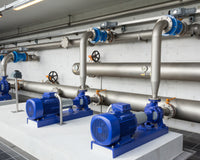
More and more domestic and industrial devices use three-phase power (3×400/230 V): submersible pumps, induction cooktops, and electric vehicle charging stations. A three-phase connection makes it possible to transmit more power at a lower current in each individual conductor, resulting in smaller voltage drops, less conductor heating, and higher efficiency of the entire installation.
- More power, lower current: for the same power, the phase current is lower than in a single-phase system (P = √3 · Ul-l · I · cosφ). This often means a smaller required cross-section or a greater thermal margin for the conductor.
- Stable motor operation: submersible pumps with three-phase motors have smoother torque, easier starting, and higher efficiency, reducing the risk of overloads and extending service life.
- Even installation loading: induction cooktops and other high-power appliances can distribute the load across 2–3 phases, reducing the load on a single circuit and limiting local voltage drops.
- Faster EV charging: home three-phase chargers (e.g., 11 kW or 22 kW AC) use multiple phases to shorten charging time and avoid “strangling” a single conductor with high current.
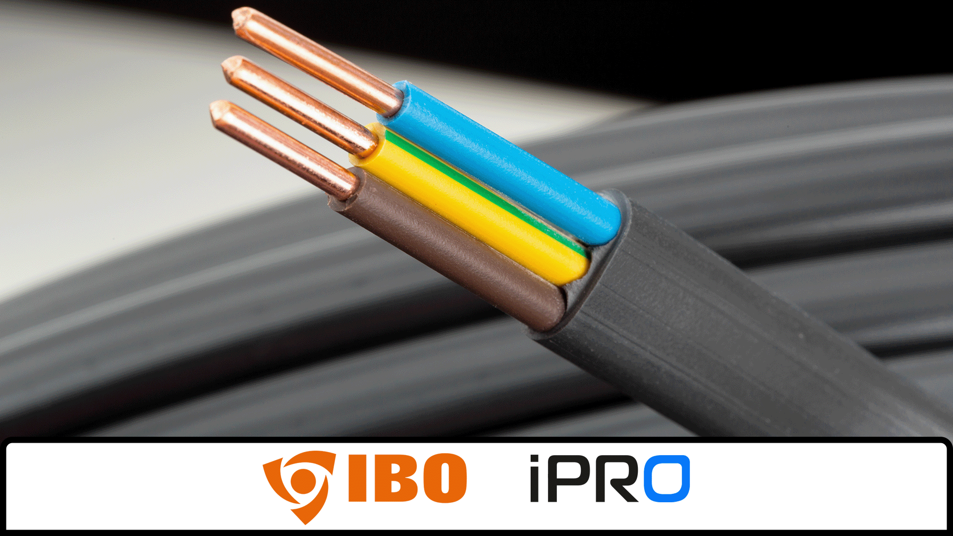
- Safety and compatibility: typical three-phase cables have 5 conductors (L1, L2, L3, N, PE). Correct selection of the cross-section, number of conductors, and protective devices (overcurrent circuit breakers, RCDs) limits heating, imbalance, and the risk of damage.
In practice, for longer cable runs and higher power loads (pumps, cookers, chargers), a three-phase system helps maintain voltage within the required range, reduce losses, and prevent protective devices from tripping. Therefore, when planning new installations, it is worth specifying three-phase cables with the appropriate cross-section and construction from the outset.
Practical conclusions
- Know your load (power/current) and route length — this is the starting point for selecting the cross-section and assessing voltage drop.
- For long cable runs or higher currents, choose a larger cross-section to limit losses and heating.
- When the environment is “noisy” (inverters, motors, radio-frequency interference) — consider shielded/twisted/coaxial cables and keep cable runs as short as possible.
- At higher frequencies/over long distances, treat connections as transmission lines: pay attention to impedance and matching.
Choose with confidence — use the calculators
To quickly check the required cross-section and the voltage drop over a given length, use our tools:
Note: Actual permissible currents depend, among other factors, on the installation method, ambient temperature, and insulation. Use the manufacturer's catalog data and applicable standards, and if in doubt, use calculators and/or consult an installation designer.