Inverter for hydrophore pumps and PV installations – application, structure and differences
The inverter is a key element of modern installations with hydrophore pumps and, increasingly, also in photovoltaic systems, where it is responsible for converting electricity and adapting its parameters to the needs of receivers. Dambat offers under the IBO and IBO brands IPRO, The inverter is mainly used as an intelligent pump controller, maintaining the set water pressure by regulating the engine speed and optimally controlling the operation of the entire system. For the end user, this means stable pressure, longer pump life and electricity savings, while for electricians - an extensive system with the possibility of configuring operating parameters, such as inverter supply voltages, control outputs and security functions.
Dambat IBO i inverters IPRO for hydrophore pumps
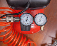
Current inverters used in Dambat solutions such as series IVR IBO or drivers IPRO, are designed to work with deep-well, surface and hydrophore pumps in home and industrial installations. Such power inverters convert energy from the network into a form adapted to the pump motor, enabling frequency and voltage adjustment as a function of the current water demand and conditions in the installation. In a typical installation, power inverters cooperate with a pressure transducer, thanks to which the operation of the inverter allows maintaining constant water pressure with changing consumption, which is especially important in hydrophore sets and irrigation systems.
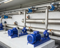
A single-phase inverter, typical for smaller home installations, allows you to power single-phase hydrophore and surface pumps while maintaining smooth speed control and protection against dry running, overload and too low or high voltage. The three-phase inverter is used for larger submersible pumps and sets with higher power, where it is crucial to fully use the capabilities of the three-phase motor while limiting starting currents, controlling the frequency of the supply voltage and stabilizing the load current. In many Dambat solutions, the three-phase inverter also enables operation in groups of pumps, where the final control stage must provide the appropriate current value for each pump depending on demand, while monitoring the voltage frequency and network parameters.
Pump inverter and photovoltaic inverter – similarities and differences
In the electrical layer, an inverter for hydrophore pumps and inverter for a photovoltaic installation have a similar functional scheme: current inverters convert energy from one type to another, usually converting direct current or alternating voltage into output parameters adapted to the receiver. In both solutions, the key factors are the inverter voltages, as well as the DC voltage in the DC circuit, which is created thanks to the rectifier section and an appropriately selected capacitor that smoothes the rectified voltage before it reaches the final stage. Regardless of the application, the structure of the inverter also includes an intermediate stage responsible for storing energy in the capacitor's electric field and controlling the capacitor voltage, which allows to stabilize the input voltage and supply voltage of the inverter.
The photovoltaic inverter is designed mainly as a voltage converter and frequency converter for direct voltage sources, which converts the direct current voltage from PV modules into alternating voltage with network parameters, so that it can power the loads or transmit energy to the power grid. In Dambat installations, the pump inverter serves as a more advanced drive controller - in practice, it is a frequency converter optimized for controlling pump motors, where the frequency of the supply voltage, the amplitude of the inverter voltage and the current value are dynamically adjusted to the required pressure and flow. In PV systems hybrid inverter additionally, it works with energy storage facilities, using direct voltage sources in the form of panels and batteries, which distinguishes it from a typical pump inverter, which usually uses a standard AC mains power source.
Inverter structure - main blocks and operating model
A typical inverter construction model includes several basic blocks: an input rectifier, an intermediate stage with a DC circuit and an output stage responsible for generating an output voltage with adjustable frequency and amplitude. The rectifier converts the AC voltage from the network into DC voltage, which is then filtered and stored by the Capacitor to obtain a stable rectified voltage at the appropriate level. The capacitor voltage value is monitored by the control electronics, which continuously controls the input voltages, the inverter supply voltages and the DC voltage source to prevent exceeding the permissible system parameters.
The final stage usually uses inverter end transistors or current-switched thyristors, which quickly switch the current voltage in the output circuits, generating a modulated alternating voltage with set parameters. Depending on the design, the final stage can operate as a classic voltage converter with PWM modulation, where changing the voltage and frequency allows you to regulate the load current and motor speed, or as a more complex converter system with energy recovery functions. In Dambat inverters IBO i IPRO solutions are used that enable precise regulation of power and pump operating parameters, which has a direct impact on the inverter power and the permissible load range at various inverter supply voltages.
Inverter diagram, terminals and measurement interfaces
An example diagram of an inverter for pumps and industrial installations shows a clear separation of power and control circuits, including elements such as the inverter control terminals, voltage input, current input and a common terminal for digital signals. The inverter terminal diagram usually includes mains power terminals, motor outputs, a multi-function digital input, an analog voltage input and an analog current input, which allows integration with pressure and flow sensors or external BMS controllers. The frequency converter configured in this way enables remote control, parameterization and monitoring of the pump operation, which is particularly important in extensive hydrophore and fire protection installations.
Modern voltage inverters also offer a measurement output and an analog measurement output for transmitting information about pressure, frequency, load current and other parameters to higher-level systems, as well as a voltage measurement output that can reflect the DC voltage in the DC link or the voltage amplitude of the inverter. A relay output or multifunctional relay output is also available, which informs about operating states, alarms and exceeding set thresholds, which allows integration with signaling, building automation or security systems. Depending on Dambat inverter models, inverter functions can also include delayed pump switching, automatic switching between pumps and dry-running test runs, which increases the reliability of the entire installation.
Electrical parameters: voltages, currents and inverter power
When selecting an inverter for a specific pump or PV installation, you should pay attention to key electrical parameters such as the inverter supply voltage, direct current voltage in the DC circuit and alternating voltage at the output, which must be consistent with the requirements of the motor or receivers. Changing the voltage and frequency of the supply voltage has a direct impact on the current value and load current, therefore the inverter power should be selected with a margin relative to the rated motor power, taking into account the nature of the start-up, cooling conditions and the method of pump operation. In installations with hydrophore pumps, it is often assumed that the inverter should have a slightly higher inverter power than the engine power to take into account momentary overloads and the specificity of cyclic operation while maintaining constant pressure.
In photovoltaic systems, it is also important to match the DC voltage sources - the input voltages result from the panel configuration, and voltage inverters must operate in a specific range of voltages and currents to effectively convert energy. The rectified voltage generated by the rectifier and the capacitor voltage indirectly determine the maximum amplitude of the inverter voltage at the output, and thus the voltage frequency regulation range and the available motor torque. When selecting the device, the power source - regardless of whether it is an AC network or DC voltage sources from panels - should provide a stable current voltage and sufficient power reserve so that the current inverters can operate in the entire required load range without exceeding the permissible current value.
Dambat inverter models, features and applications
Dambat inverter models from the IBO i families IPRO are designed for a wide range of applications, from home hydrophore installations to industrial systems and irrigation systems that require precise control of the pump operation. The available inverter models allow the operation of single-phase and three-phase pumps in the power range from fractions of kW to several kW, which allows the configuration of both simple sets with one pump and complex systems with several pumping stages and cascade control. In many applications, a single-phase inverter is used in single-family buildings, while a three-phase inverter is installed in larger facilities and technological installations, where direct current appears only in the intermediate circuit, and alternating voltage is used on the supply and output sides.
In solutions with pumps deep-sea and hydrophore Particularly important are the functions of inverters responsible for pressure regulation, protection against dry running, engine temperature control and supervision of voltage frequency and load current. In some variants, a hybrid inverter is also used, which combines the possibility of power supply from the grid and from alternative sources of direct voltage, which may be useful in facilities with their own PV installation and hydrophore set. Thanks to the extensive functions of inverters, it is possible to reduce water hammer, extend the life of fittings and reduce energy consumption, which translates into stable and economical operation of the entire water system.
Control inputs/outputs and integration with automation
The modern Dambat pump inverter provides a rich set of interfaces, including an analog voltage input, an analog current input and a current input for connecting pressure, level or flow sensors, which allows the implementation of advanced control algorithms. Additionally, the multi-function digital input allows you to connect start/stop signals, manual operation, priority modes or external interlocks, while the inverter control terminals are clearly separated from the power circuits, which facilitates the design of control cabinets and security systems. Thanks to this, the frequency converter can be easily integrated with superior PLC controllers and BMS systems, without the need to use complex intermediate systems.
On the output side, in addition to the classic relay output, there may be a multifunctional relay output and a multifunctional output for signaling emergency states, working in automatic mode or achieving a set pressure value in the installation. The analog measurement output and the voltage measurement output allow information on parameters such as voltage frequency, current voltage or load current to be transmitted to monitoring systems and recorders, which facilitates the diagnosis of faults and optimization of system operation. As a result, the functions of the inverters go beyond simple speed regulation, creating a complete control system with the possibility of remote supervision, data archiving and adaptation to changing operating conditions.
An example diagram of an inverter in an installation with a pump and PV
An example diagram of an inverter used with a hydrophore pump assumes that the alternating voltage from the network goes to the rectifier, where it is converted into direct current voltage, and then, through an intermediate stage with capacitors, it goes to the final stage generating adjustable voltages of the inverter. In such a system, the rectified voltage and capacitor voltage are continuously monitored, and the change in voltage and voltage frequency takes place as a function of signals from the analog voltage input or analog current input, which represent the current or pressure value from the sensors. The common terminal and the inverter control terminals create a logical connection structure, where all control and measurement signals are organized to make service and configuration as easy as possible.
In a photovoltaic installation, the voltage inverter functions as a converter that accepts input voltages from DC voltage sources such as PV modules and energy storage, and then voltage inverters generate an AC voltage matched to the grid, with a specific voltage frequency and amplitude. In the case of a hybrid inverter, it additionally manages the energy flow between the grid power source, energy storage and receivers, which requires precise control of the load current and continuous analysis of values such as current voltage or the value of the storage charging and discharging current. In practice, the operation of a three-phase inverter in PV and pump systems is similar, but adapted to different load characteristics - in one case, these are general receivers, in the other, pump motors with specific characteristic curves.
Summary – when to choose a specific type of inverter
In installations with hydrophore pumps in residential buildings, a well-selected single-phase inverter is usually sufficient, the inverter functions of which are focused on pressure regulation, engine protection and simple start/stop control, while maintaining compatibility with typical power sources. In larger facilities, industrial plants or systems with several pumps, a three-phase inverter with appropriately selected inverter power and advanced configuration options will ensure better control of the load current and lower energy losses during continuous operation. In PV systems, especially those with energy storage, a key role is played by the hybrid inverter and dedicated current inverters and voltage inverters, which are responsible for the effective conversion of energy from direct current to alternating voltage in accordance with the requirements of the grid and receivers.
The selection of a specific device should always take into account the structure of the inverter, the inverter construction model indicated by the manufacturer and a detailed sample inverter diagram along with a description of the terminals and interfaces, thanks to which an SEP-licensed electrician can properly configure the multifunctional digital input, voltage input and current input. It is also important to analyze parameters such as the inverter supply voltage, voltage frequency, DC voltage in the intermediate circuit, as well as the available measurement output, relay output and analog measurement output, which allows for full integration with automation and monitoring systems. By choosing Dambat solutions, the installer gains documentation support and instructions that describe in detail the operation of the inverter, the inverter diagram, terminals and all functions of inverters for hydrophore pumps and other applications.
FAQ – frequently asked questions about pump and PV inverters
How does the inverter work in an installation with a hydrophore pump?
The inverter in an installation with a hydrophore pump analyzes the signal from the pressure sensor and, on this basis, adjusts the frequency and amplitude of the voltage supplying the pump motor, regulating its rotational speed. Thanks to this, it is possible to maintain constant pressure in the installation, regardless of variable water consumption from different collection points. This limits the number of cycles of turning the pump on and off, reducing mechanical and electrical wear of the device. Additionally, inverter functions include protection against dry running, overload and voltage spikes, which increases the reliability of the entire system.
What is the difference between a pump inverter and a photovoltaic inverter?
The pump inverter is optimized for controlling electric motors, where the most important is smooth regulation of frequency and voltage as well as control of the load current as a function of pressure or flow. The photovoltaic inverter mainly functions as a converter that converts the direct current voltage from the panels into alternating voltage in accordance with the network parameters and receiver requirements. In PV installations, the priority is high processing efficiency and synchronization with the grid, while in systems with pumps - stable pressure, operational safety and mechanical protection of the installation. The hybrid inverter in PV systems additionally manages the energy flow to and from the energy storage, which is usually not required by a standard pump installation.
How to select the power of the inverter for the pump?
The power of the inverter should be at least equal to the rated power of the pump motor, with a small margin recommended to account for transient overloads and starting conditions. The selection also takes into account the inverter supply voltage, voltage frequency and expected load current in typical and extreme operating conditions of the installation. In the case of pumps with difficult starting or operation in difficult conditions (large differences in lifting height, frequent starts), the power reserve of the inverter should be greater. Manufacturers such as Dambat provide selection tables and instructions that describe the recommended selection of inverter power for specific pump models.
What is the importance of measurement inputs and outputs in the inverter?
Measurement inputs and outputs in the inverter allow integration with sensors, superior systems and monitoring devices, which enables precise control and diagnostics of the installation operation. Analog voltage input, analog current input and current input are most often used to connect pressure, level or flow transmitters that determine how the pump speed is controlled. In turn, the measurement output, analog measurement output and voltage measurement output allow transmitting data about voltage frequency, current value and voltage in the DC circuit to monitoring systems. This makes it possible to quickly detect anomalies, optimize operation and record the pump load history.
Why are capacitors and rectifiers used in the inverter?
The rectifier in the inverter is responsible for converting the alternating voltage from the network into direct current voltage, which is then smoothed and stored in the intermediate circuit capacitors. This configuration ensures a stable rectified voltage of an appropriate value, based on which the Final Stage can generate a regulated alternating voltage at a given frequency. The capacitor acts as an energy buffer, compensating for short-term fluctuations in voltage and load current, which improves the stability and reliability of the inverter. The use of properly selected rectifiers and capacitors is crucial for the life of the device and the quality of the voltage supplied to the motor or network.